Showing posts with label Solidworks. Show all posts

Saturday, May 16, 2020

A Cheap and Effective Way for Ceramic 3D Printer

Hi there!

I know I'm not here for a long time. I noticed that I completely forgot my blog when someone of you emailed me. So I wanted to make a good return. That's why I came up with a new design 3d printer!

First of all, I have to point out that the 3D printer has attracted my attention for a while. In my studies, I was trying to synthesize a kind of cartridge material suitable for these printers in general. In other words, I was more confident on my own behalf for the science of material, which is my specialty, by virtue of my profession. In this sense, I realized the 3D printing of the polymeric matrix material I synthesized. As most people who are interested in this matter know, buying a 3D printer that prints plastic/polymer is quite easy and cheap. You order online, pay online, oh welcome to internet age Mrs Gergeroglu,  your 3D printer is in your lab now!

But when it comes to 3D printing of ceramic materials, there is an incredible increase in prices depending on the type of devices. As an explanation for the price I mentioned,  access to such a device for a doctoral student like me is unimaginable.


But ultimately I have to think solution-oriented analytical. Because I am synthesizing bioceramic material and it is one of my professional passions to see my work in a final application area. As will be known, most of the implants are designed with ceramic based materials. If a complex-shaped implant is involved, production by conventional methods is challenging. That's why 3D printer is an extremely promising technique.

For this reason, I made a wide-ranging internet research to design my own 3D printer. As a result of this research, I met Jonathan Keep. He had designed a cheap and simple clay 3d printer.  So I redrew and scaled it through Solidworks 2017.


All of my drawing pieces are accessible and free. You can download and review here!

Apart from the mechanical parts of this design, if I can provide the software information I need someday, I hope that I can print the biomaterials I've synthesized from my printer!

As the world evolves into a terrible place, don't forget to stay home and dream!

C ya!
H.


Thursday, February 9, 2017

Rack Gear

Hello there,
Today I am going to talk about the rack gear!

This gear translates circular motion into linear motion. Thanks to the teeth opening to a flat surface, the movement of rotating gear is converted in one direction. It is usually used in automatic doors and drills.

Rack gear manufacturing can be done by using different materials according to usage place and working conditions of the gear. Plastic racks can be used for quiet, non-lubed, non-high-load work environments. They are generally used in many areas such as chemical facilities, paper factories, sugar factories, mining industry, automotive, textile industry, aviation, medical devices, food industry. Plastic Rack Gears compared to metal gears lighter and economical. Also, they are quiet and no need for lubrication. In addition to, they have corrosion and resistance to acidic environments.

It's okay here. Now let's look!


My studies are in this link. 
C ya!

Tuesday, February 7, 2017

Automotive Series-1

Hello,
I decided to organize a series of automotive parts. This is the first series for now.😊

Engine Valve


  • Used for internal combustion engines of motor vehicles.
  • It is used to control gas flow in engines.
  • Used to control the intake of air into the engine and the emission of burned exhaust gas
Valves used in today's modern revolving high-compression engines must be long-lived and resistant to high temperatures. For this reason they are made of special steel alloys. The intake valves are made from chrome-nickel steel alloys, while the exhaust valves are made from heat-resistant steel alloys (stellite). In some engines both can be made from the same material.

Engine valve solidworks part is here


 Air Turbo


  • It is not exposed to very high temperatures
  • It is usually produced from aluminum.
  • Air from the air filter passes through here.

Air Turbo Solidworks Part is here


Engine Air Filter


  • During engine operation, large quantities of air taken in the cylinders are filtered to remove dust and dirt.
  • Paper filters are used today.
  • It can filter even very small particles at a sensitivity of 5 microns.


Engine air filter Solidworks Part is here.


Engine Cylinder Head


  • Closes the top of the cylinders
  • Build combustion chambers.
  • Some of the exterior parts are housed
  • It is usually produced from aluminum.

Engine cylinder head solidworks part is here


C ya!

Sunday, February 5, 2017

Simple aircraft design

Hi, there!

I made a simple aircraft design. Sole piece. Here.


C ya!

Chemical Reactor

Hello friends,
What's up? Although I was busy this week, I draw a chemical reactor in Solidworks. Let's talk it!

The reactor is a special type of container commonly used in the chemical industry.
Chemical reactors are specially designed products that operate under full pressure and temperature conditions with full vacuum. The chemical reactors use in various chemical operations such as solid dissolution, product mixing, chemical reactions, bulk distillation, crystallization, liquid or liquid extraction, and polymerization.  They are used in studies where chemical reactions are required in sectors such as petrochemicals, the pharmaceutical industry, paper, food, and beverages.

A typical Reactor is a vessel consisting of a mixer and an extensive heating and/or cooling system. Liquid and solid objects are filled through the connections in the top cover of the Reactor. Steam and gasses are evacuated with the help of the connections at the top of the Reactor. The liquid is usually evacuated from under the Reactor.

The dimensions of these containers can range from 20 liters to 40,000 liters. It is usually manufactured from steel, stainless steel, glass-clad steel, glass or alloy.

Learn about stainless steel

Stainless steel is iron-carbon alloys containing high Cr and Ni. Their compositions contain at least 12% Cr.  And the chrome protects it against rusting. When the chrome element in stainless steel is exposed to oxygen (which means oxygen in a normal atmosphere), it immediately forms a chromium oxide (Cr2O3) passivation layer. This layer is so thin and completely obstructing oxygen penetration. In addition, the clearance to be created in case this layer is torn, opened or scratched for any reason, layer a very rapid reformation of the layer itself. (This is called passivation) Therefore, stainless steels have high corrosion and oxidation resistance.

Okay, let's look at the drawing.😊

Here we see reaction tubes

And an explode view

 And a completed reactor


My studies are in this link. 
C ya!

Tuesday, January 31, 2017

Mechanical Bench Vise

Hello!!

I'm going to talk to you about the mechanical bench vices today.


What is mechanical bench vise?

It is mounted on a table and serves to fix the parts to be processed. The clamped part does not slip due to the jagged in the vise jaw.
Vices,in the market, measure according to the jaw opening. For instance, when say that is the vice has 200 mm jaw opening, it means maximum jaw opening distance. If you know the size of the largest piece you'll tie, you can choose the vice as the jaw opening will cover this part. There are three types of vices; The most important of these is the bench vise.

Some properties of bench vise

  • It can be attached to a table, stand or machine table.
  • It is fixed because it is not moved.
  • Almost any kind of material can be connected to it.
  • It gives a very strong tightening.
  • There is a threaded shaft attached to a handle arm.
  • When we rotate the arm clockwise, we will obtain tightening. In this situation, we loosen it in the opposite direction. 
  • The port in the jaws are of warded construction and can be removable and mountable. *
It's okay here. Let's look at the mechanical bench vise I'm drawing now! 😋

 Here is the vice's body
 The other piece of the jaw
 Guide lever


TAA-DAAAA!! I put the pieces in place! Here is the last picture of the mechanical bench vise.

I've upload my work here. You can download it.

C ya.


Friday, January 13, 2017

Hobs..

Hey!
Hello again. Today, we will talk about hobs. :)

What's milling?
Milling is a process which made by removing the sawdust from the workpiece. It provides that made by linear motion with a multi-tip tool rotating around its axis. In today's milling process, the tool can move to the workpiece in almost every direction. The cutting tool has many cutting edges and each edge has a certain amount of chip removal capacity.The advantages of the milling machine are high machining efficiency, good surface quality, precision and flexibility in shaping.Milling is a process usually used for machining plane surfaces, upright corner and channels.

Process the material
If you want to process a material, you should choose a cutter that is suitable for your material. So, you should use a harder cutting tool from your material. Okay? Therefore, the cutting tool material is very important in terms of machinability. Cutting tools developed with technology is favorable for our work in many applications. But the main feature expected from cutting tool material is the higher movement rate at higher cutting speeds. The cutting tool must have high abrasion resistance, high toughness and high red hardness in order to be able to do this. Despite the diversity of cutting tool materials, the most commonly used tool materials are HSS (high speed steels) and carbides.* But ... High-speed steels are not as hard as carbide, although they are much toughness than carbides.  In addition, it prolongs process time. Alright! How should  material of cutting?


Required features at a cutting tip

  • High hardness. (Low hardness causes the tool profile to deteriorate.The tool tip will be deformed.The tool material must be harder than the hardest component of the workpiece)
  • High durability
  • High wear resistance 
  • High fatigue resistance 
  • It must be compatible with the sawdust (ie, must not occur a reaction between the sawdust and the cutting tip during process.)
  • Low Expansion Amount
  • High elastic module (If elastic modulus increases, stiffness increases. So, the higher the elastic modulus, the less deformed it becomes. I do not wanna change the tweening of cutting tip during the process. Otherwise, How can i handle to the workpiece?)
  • High thermal shock resistance (Rapid heating and cooling occurs during process. Cutter tip must be resistance this.)
  • High toughness (Cutter tip must not to be affected by mechanical shocks which occurs during the process)


As you can see, there are many features and it is still difficult and expensive to find them together in today's technology. For example diamond, the queen of cutting tools, has narrow application area cause of is expensive despite carrying a majority of these features. We needed to find an alternative to this and we produced high speed steels. But I said up there. It will spend your time. We need to find something more optimal.

Here it is,
We had to find a cheap cutting tip to replace the diamond. And these are carbides. Imagine abrasion resistance of carbides which is thought to replace diamonds. Moreover, the life of carbides is longer than HSS. So our hero are carbides.  :) 95% of the cutting tools produced from carbides are tungsten carbide-based.

What is Tungsten Carbide? (WC)
The general composition of the Co-Cr-W alloy, referred to as Tungsten's most widely used Stellite; 38-46% Co, 25-35% Cr, 4-25% W and 1-3% C. The hardness of the alloy ranges from 40-60 HRC depending on the ratio of tungsten and carbon. No heat treatment is required. This alloy has features such as high hardness, high wear, oxidation and corrosion resistance and excellent red hardness. The combination of these properties makes this alloy using suitable as cutting tip at the milling machine.

Metallurgical references belong to me:) Alright. We are now passing this issue. Let's come to my drawings. I designed cutter tips which has several different geometries at Solidworks.

VOILAA!!


I have uploaded  my studies this link. You can download and look at it. ^^
C ya.


*Barkın B., 2005, Cnc Freze Tezgahlarında Kullanılan Karbür Parmak Freze Takımı Geometrisinin İşlenebilirliğe Etkilerinin İncelenmesi, Marmara Üniversitesi, Fen Bilimleri Enstitüsü, Makine Eğitimi Anabilim Dalı, Yüksek Lisans Tezi, s.6-12

Wednesday, January 11, 2017

From where to where..

The only significant parts that use the vehicle's on site contact is tires. It's made of a combination rubber, steel wires and chemical supplies. It allows the load and the vehicle to be transported through the air that is pushed into the tire.
The working principle of tires can be described as simply defeating the frictional force by means of a rotary motion with an axle. In order to be able to make a turning motion on a surface, tires are absolutely necessary to be exposed to gravitational force or another external force.

Do not take serious that this was done before. Never give up to enhance.

The back zone of tire is the part of contact to road. When the tire became age, traction is reduced. Over time, the pattern on tire wears out and becomes unusable. Tread depth is very important for this reason (reference , available online: 11.01.2017)

On the other hand, over the world, over 15 million tonnes of rubber are produced annually; About one of three which is natural rubber. And two out of three is artificial (synthetic) rubber. Rubber is actually a tree name. The material obtained from this tree ( it's name is latex and it's natural rubber) has been used in the industry. Because of the use of natural rubber a lot, the synthetic rubber was obtained by the Germans in 1906 so as to procure the rubber at a very cheap and abundant quantity.

Where is it used?

The use of rubber has increased dramatically with the development of highway transport.  Rubber was first used in bicycle wheels. Then, it was used in the wheels of trucks,planes,tractors and similar vehicles. Apart from these, rubber are used in many different sectors such as waterproof clothing, toys, upholstery materials,blow-up beds etc.

Why is it so much preferred?

The most important feature of rubber is that it has a high elasticity. It is dissolved in rubber naphtha, carbondissulfide, carbontetrachloride, turpentine, ether, gas oil, petrol and similar dissolving liquids. The rubber has properties such as softness, durability, elasticity, water and air impermeability, adhesion and resistance to electricity. Among the physical products, rubber is a very important product because of these properties (reference, available online: 11.01.2017).

Ok. That's enough information :) Now I should show you the tire of tractor which I have drawn at Solidworks.


There was a line before everything :D

     and the mirror command...

then I used revolve command to get bodies of tire
I must open a newplane on the bodies of tire. It's too important for treads.
.
then i created curves via spline command..


Using  extruded, extruded cut,circular pattern, chamfer and fillet commands..


I made a very vibrant tire of tractor ^.^

If you want to follow my commands, I have uploaded my solidworks part in this link.

C ya.

Sunday, January 8, 2017

Simple Pieces

Hi,

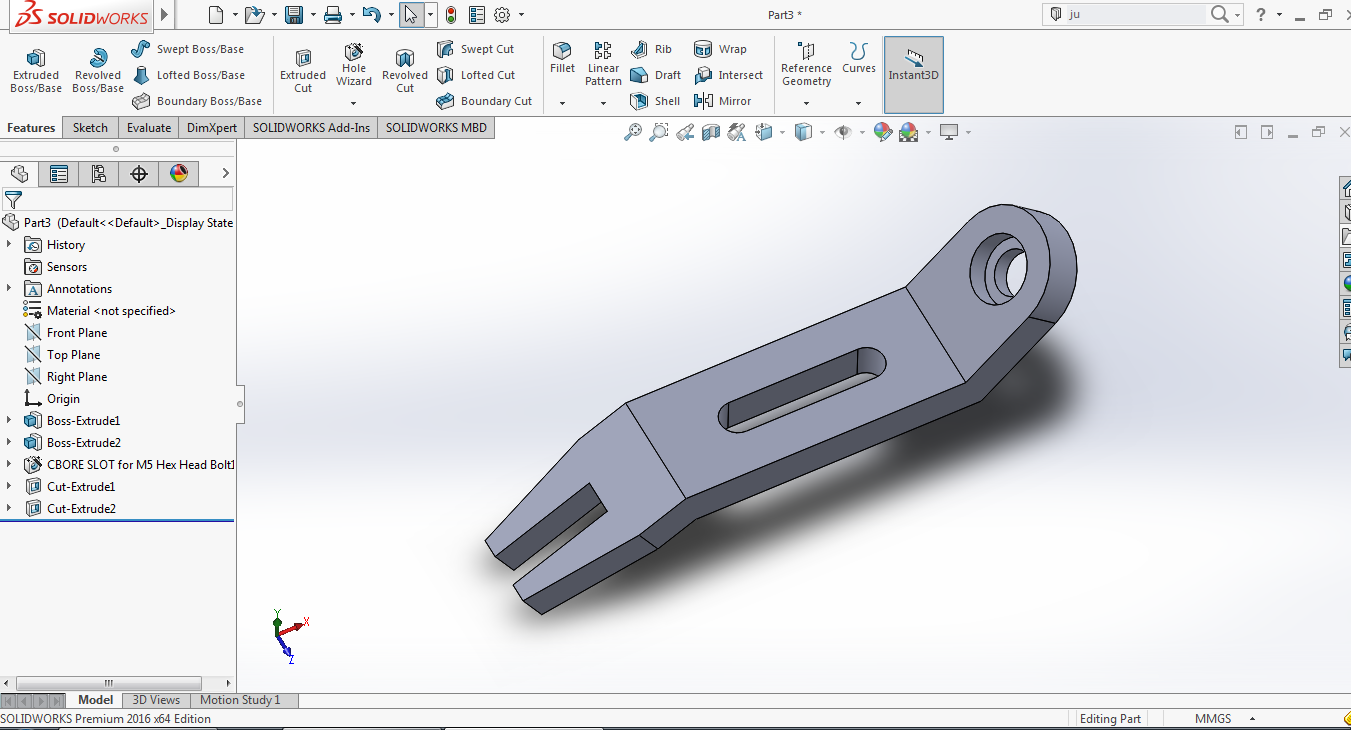
If you are new to SolidWorks like me, you can draw simple pieces to get used to the commands. Now I'm going to show you the simple pieces that I've drawn.


 You can draw by following the order on the left.


Click on the link for more: http://www.megafileupload.com/cqY2/ödev.pdf
c ya.

Thursday, January 5, 2017

3d Printer

Hi,
It's my first solidworks job. You can access here-->  https://grabcad.com/library/3d-printer-with-interchangeable-parts-1

Are the hinges settle? NOOOOO!!! It made me mad! -____-


Are you seeing? Mate is always trouble for me :(

but part of Z was very entertaining.