Showing posts with label Autocad. Show all posts

Wednesday, January 18, 2017

Nuts & Bolts

Hi, there!!

Pausing my drawings a few days because of the my master thesis. But i'm again here with a new and amusing issue.  Okey. I will commence to talk about nuts and bolts immediately! Alright. Initially, we must talk what's the nuts and bolts?

Bolts are the most widely used resolvable machine elements. The bolt is made by pulling a screw into a cylindrical bar. In principle it is obtained by helically wrapping a profile on a cylinder with equal pitch.The wedge effect is utilized in the anchoring process.  Moreover, screws are the easiest way of the spinning motion translate to forward. The screws are normally right helical. In this circumstances, when the nut is turned clockwise in the bolt  the connection is tightened, otherwise it is loose. The bolts and nuts run on the principle of force connection. Generally, forces of tension and compression in the axial direction compel the bolts.They are operated under tension forces(*).

What is the tension force?
We come to the most important issue that a material engineer should know. It is a common term used in strength calculations. Okay, but what is this?

Let's think of a simple bar. We will load forces which is  parallel to the axis of the bar, equally magnitude and opposite to each other on both ends of this bar. If we want to calculate the tension in this bar according to the accepted method of sectioning, we will have to take a section from where the bar will be calculated. Let's take this section perpendicular. We will take into section the external force that affect. Thus, we will get  single internal force impacting on parpendicular to the section. According to the equilibrium of the internal forces, the reaction force  will be produced against  action force.  And both will be the same magnitude. This tensile force pair will compel the two surfaces of the cross section to seperate from each other, ie to pull one from the other. According to this compulsion, materials exhibit different fracture. We classify the materials as ductile / brittle according to shape of fracture. If the material shows elastic deformation and suddenly fracture, is brittle. But if material demonstrates waisting and plastic deformation, is ductile.

Let's go back.
Advantages and disadvantages of bolts&nuts
• Highly reliable operation
• Repeatedly removable and installable
• It is very easy to supply because it is completely standardized
• Manufacturing is easy and cheap
• Easy to replace
• Stress accumulation occurs due to geometry
• Sensitivity is not sufficient in some applications
• Thawing can be prevented, but loosening can not be avoided(**).


The bolts are classified according to the German Standardization Institute(DIN). Generally, St37, St42 and St70 steels are used. These steels are named according to the tensile strength. That is, the strength of St 37 steel in the 1 mm2 cross-sectional area is 37 kP / mm2 or about 370 N / mm2. Materials such as Al alloy, brass, teflon, polyamide are also used for various purposes bolts. If there is no big force in the manufacture of the bolts, St37 steel is usually used. St37 is a plain carbon steel.

About plain carbon steel
Low carbon steels involves cover the greatest amount of world steel production. Low carbon steel are used  bolts, nuts, reformable machine parts and in construction sectors. The steels in this group are steel containing 0.20% carbon.  In addition to,  this steel also include components such as very few amount of  Mn, Si, P, S. Their mechanical properties are limited. They are cheap and easy to shape. Their hardening ability is low.

It's okay here. Now let's look at my drawings.

 6 corners shafts 

Right-helix

How are we going to squeeze these machine elements?
Tightening and unscrewing of the bolt connections is done with a spanner or screwdriver. Wrenchs and screwdrivers are called according to heads or ends. I has draw a fork spanner and a flat screwdriver here.


 Flat Screwdriver

Fork Spanner

The files are here.


I also want to you see my little friend who accompanies my studies. 😊
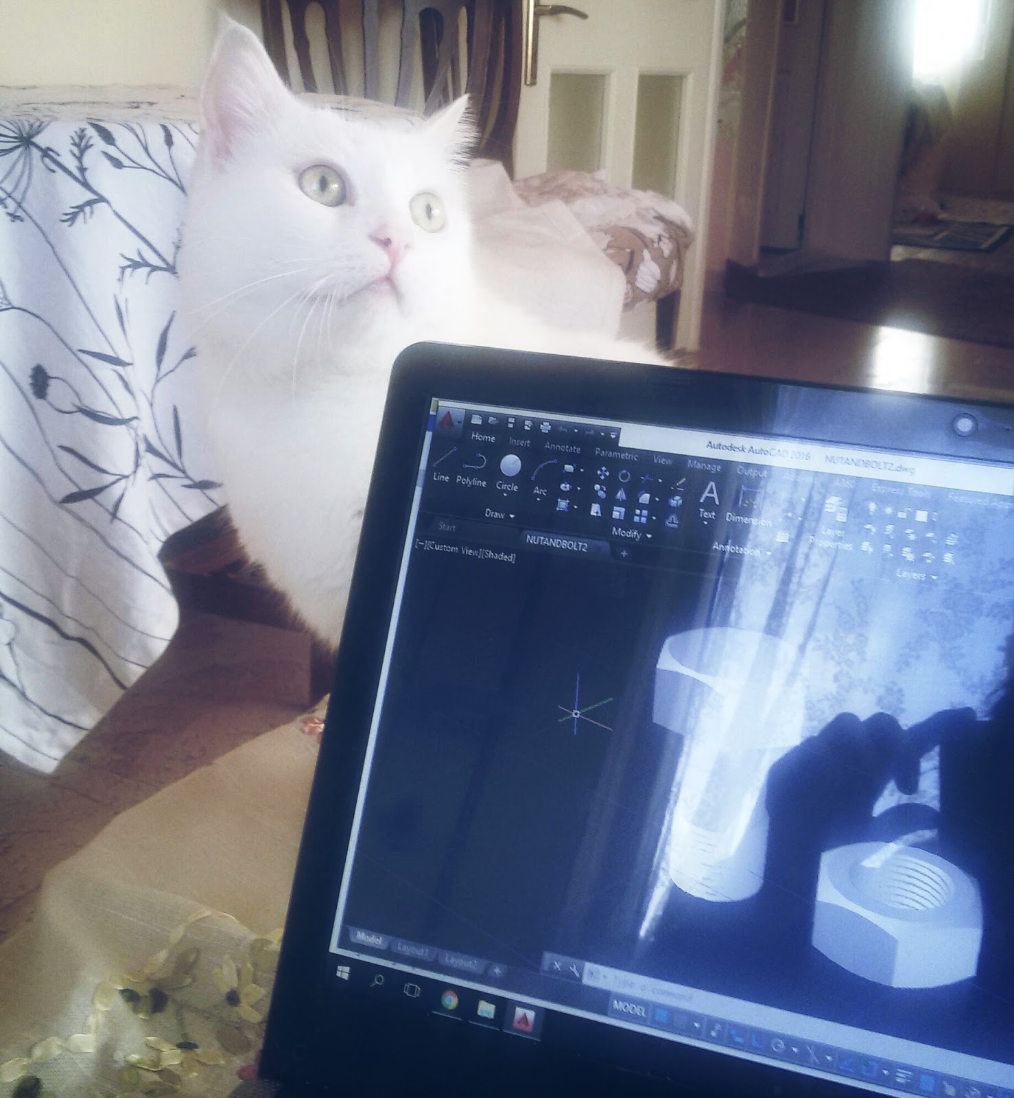


C ya. 😊😍💜😽

Sunday, January 8, 2017

what a beatiful kamikaze :D

Hey hey!!

Now, I'm going to tell you about jet engines. Because I drew a simple jet engine in AutoCAD 3D. Before talk about the drawing, we must talk about what is mechanism of jet engines.

The jet engine squeezes the air from the atmosphere and burns it with fuel. This produces a pushing force in the reverse direction by rapidly blowing out the gases resulting from the heating. With this force, the vehicle to which the motor is connected is allowed to move. These motors have been developed in accordance with Newton's laws of motion. According to this law; Each effect produces a response of equal magnitude and reversal.

If you ask the question of what is the power to fly, we immediately say engine. This answer is correct but incomplete. There are many factors that push it forward. The movement of a plane is basically by increasing the momentum. The mentioned momentum increase is provided by these:

  •   By compressing a turbojet engine air first and then expanding it by heating,
  •   By accelerating the air backward with a propeller,
  •   Modern, high by-pass turbojet engines are obtained partly by expansion in the turbine and partly by propeller speeding.

Propeller transforms the mechanical energy produced by the internal combustion engine or the turbo engine to pulling force by the way of the air mass accelerating  in the direction opposite to the direction of the aircraft. The propeller is actually a straight or sprung wing section (airfoil). The reason for being twisted and thinning is to create a uniformly distributed thrust throughout the propeller. Because the flow of air flows over the propeller, its maximum velocity is at the tip. In this case, when a fixed section propeller is used at high speed, it causes major problems at the tip.*

*This informations are from turkish magazine which is Hezarfen Aviation Magazine. You can connect to this link  (available online: 08.01.2017)


Okey. Now we can look my drawing.

My wings of the propeller is here. Firstly i draw the wings, then i wielded polar array command. It has 21 wings.


Top view of wings ^__^


Then, I made four circles on the wings to form the house of the propeller

 Turn it around a bit. yeppa.


 And with the LOFT command... Our work is about end :)


YİİİPPAAAAA!!! It finished!! I always use the layers. Do you know why? It always makes my job easier.

 c ya. 

Friday, January 6, 2017

Roll and roll


Steels that can be deepened in hardness by water are called tempered steels. These steels are produced for use in machine production. The most important difference of these steels from the production steels is that they are deeply (fully) hardenable steels. Bearing steels are also included in this group.

What is AISI?
The best thing to do to understand a thing is to classify it. Classifying according to the alloy element and physical, mechanical, chemical properties etc., makes our work easier. For this reason I call AISI is the identity card of the materials.

What about the AISI E 52100?
It is a steel alloy type containing high carbon and chromium. It is usually used in bearings. The process is easy. Carbon ratio is 0.980 - 1.10%. If you want more, you can look for ID Card :) (available online 06.01.2017)

Okey. That's enough metallurgy. Now I can tell you why I'm talking about the ball-bearing  Firstly my license thesis was on the mechanical behavior of the ball-bearing steels at high temperatures. Maybe,for this reason I have a special interest. But here I will tell you about my drawings. Yeah. I drew a roller in Autocad 3d.


Firstly I sketched the sections and then I made the bearing house with the revolve command


I used the layers. I used pink and purple hue as it's girls colours :)
I'm angry about idea that engineering is just male business. Is just male business? Oh, really? Womans can do everything!


TAAA-DAAAAAAA!!!! 
We got a cute ball-bearing.

Thursday, January 5, 2017

Turn and turn!

Hey!
I think my autocad works are better than my solidworks works. Cause of this, solidworks is more complex than autocad or I'm hard put to do Solidworks. I don't know the reason! But I will learn Solidworks anyway, this part are from Autocad and it has two dimension.

Guess what is this?


Have a nice trip :))